In a slight departure from frame building skills, I decided to practice using our lathe to make a headset spacer to remedy a bike fit issue on my Colnago.
With the available steerer length, a 10mm spacer would put the stem slightly too high above the steerer – which in practice was fine, but aesthetically it just looked like a big stack under the stem.
A 5mm spacer underneath the stem would not work as the top of the steerer would be flush with the top of the stem, with no space for the headset top cap to be attached and pre-load the bearings.
So, after some careful measurement, an 8mm spacer would be the best option to have the stem at my ideal height while still being low enough to have the headset top cap sit just on top of the steerer.
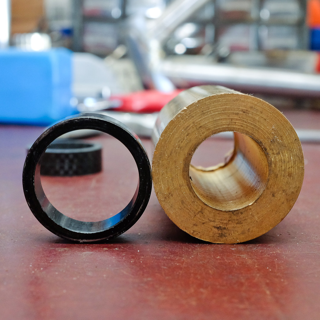
So, I needed a spacer 8mm tall, with an inside diameter of ~25.5mm to fit around the 1″ steerer, and an outside diameter of ~32mm to look flush with the stem’s diameter.
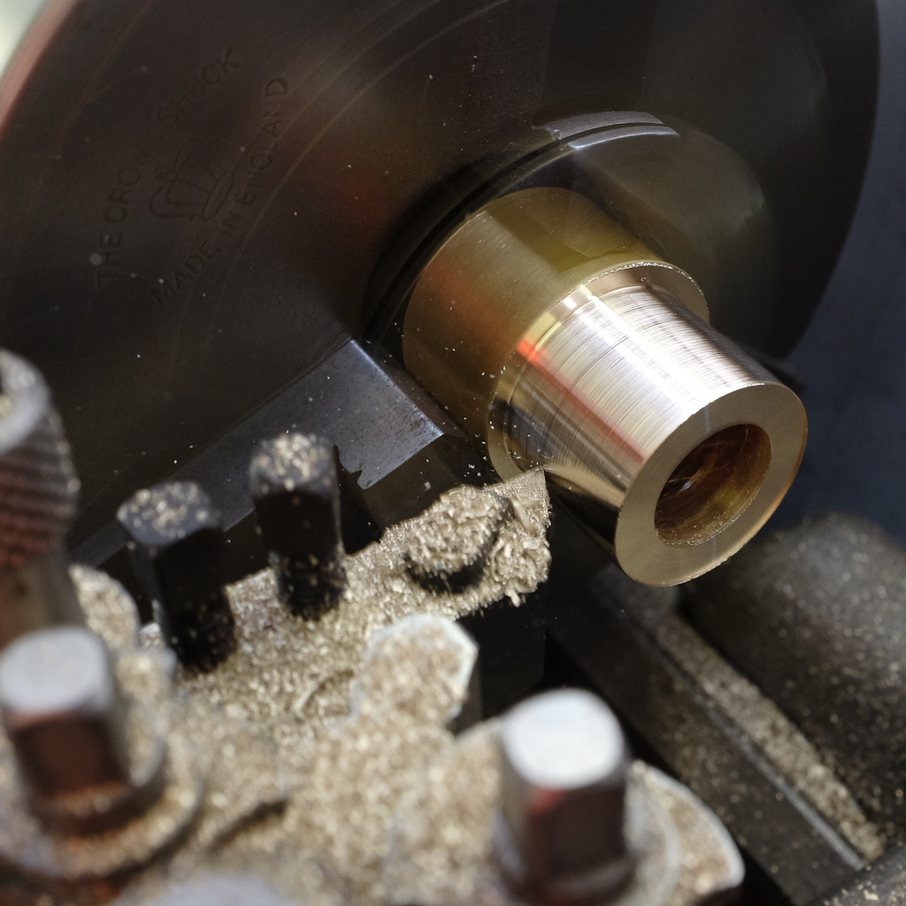
With a selection of offcuts available from Quang’s work, I used a scrap cylinder of brass of ~38mm OD and had been drilled at ~20mm ID.
The first step was to have a nice flat face on the end of the scrap material. This was done by having a right-hand tool remove material from the face of the piece. This was aided with the power feed function of the lathe.
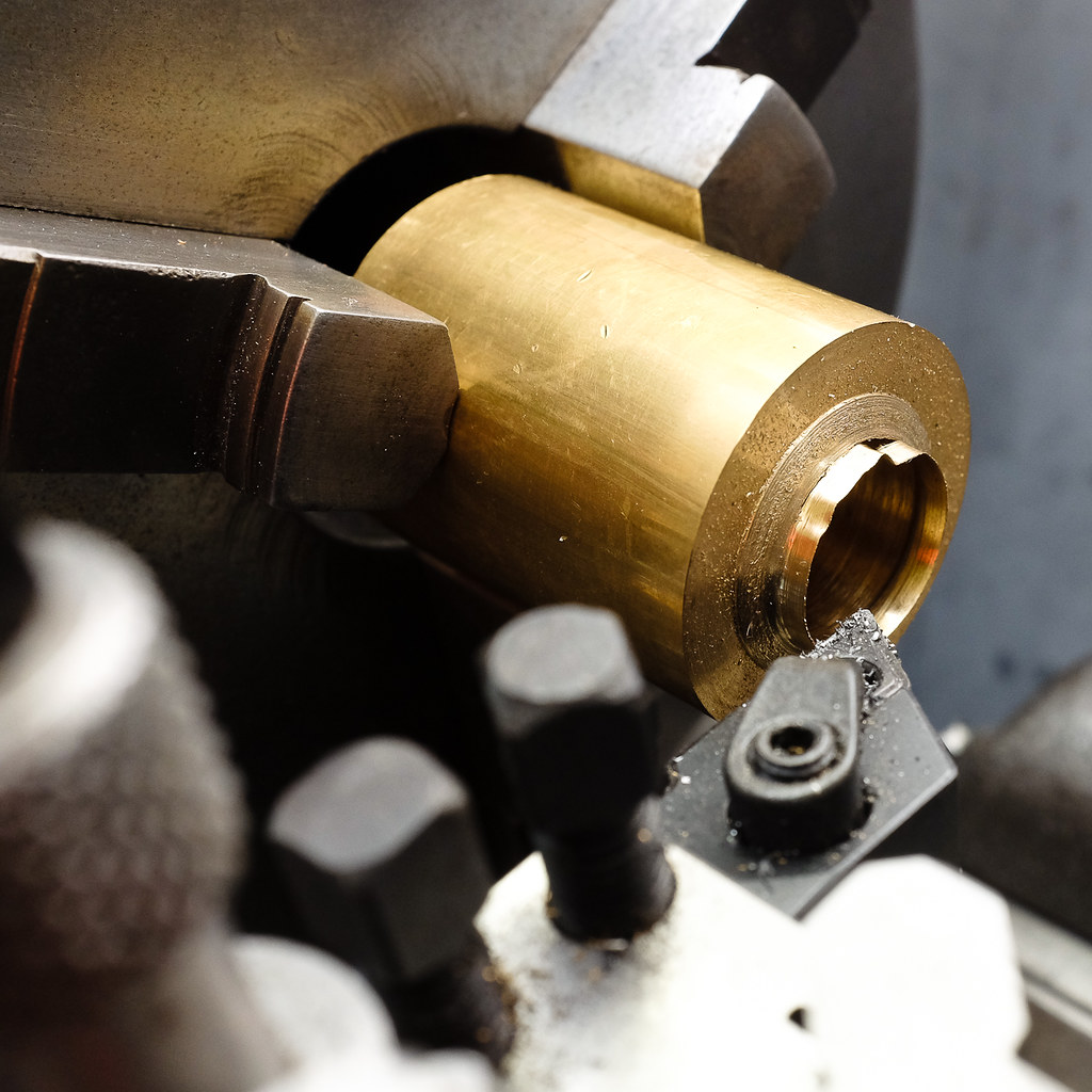
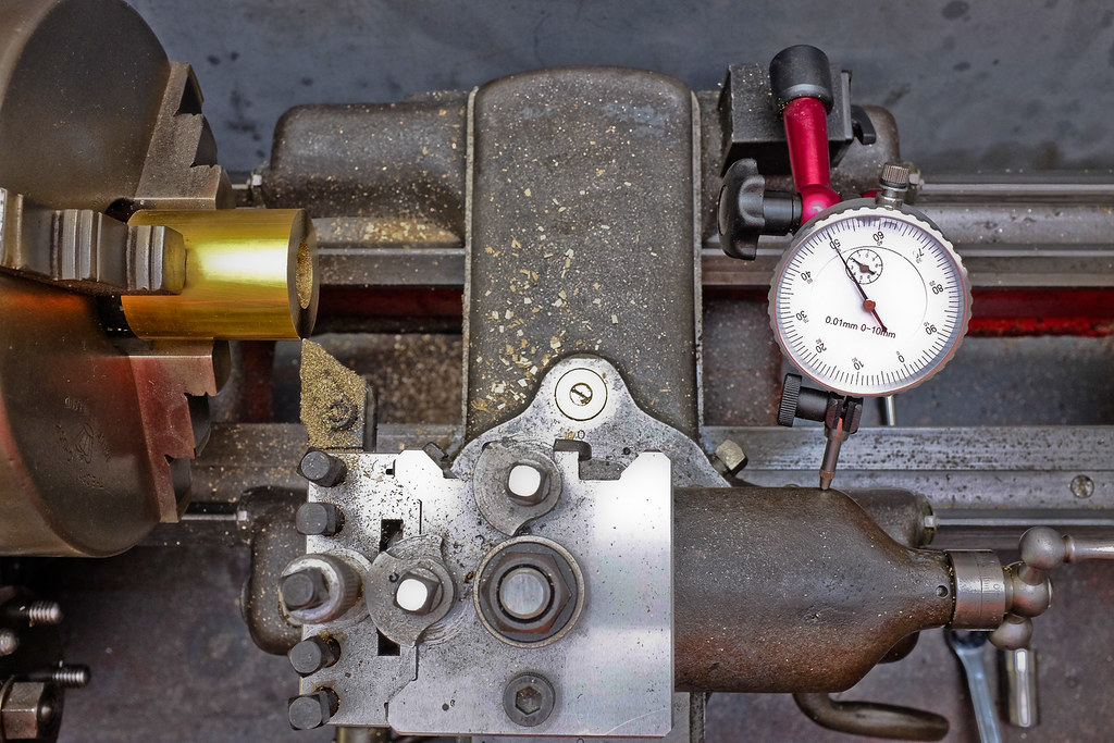
Next was to turn down the OD to the required 32mm. As our lathe uses imperial dials, Quang helped set up a metric dial indicator on the cross slide to show how much material the tool was taking off in that pass. I took 0.5mm at a time, i.e. 1mm from the diameter. Every few passes I checked with the micrometer to ensure I was getting close to the 32mm target.
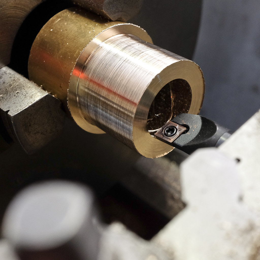
Had I needed to bore the brass, I would have started with a center drill on the tailstock, then work my way up to the largest drill bit we had, then used the boring bar to do the rest as I did. I used the boring bar again with the micrometer to take material off, this time 0.25mm on the dial meant 0.5mm per pass. In addition to checking the ID with some verier calipers, I used an inch diameter scrap tube to ensure the fit wasn’t too tight nor loose. Power feed was used in the final cuts for a smooth finish.
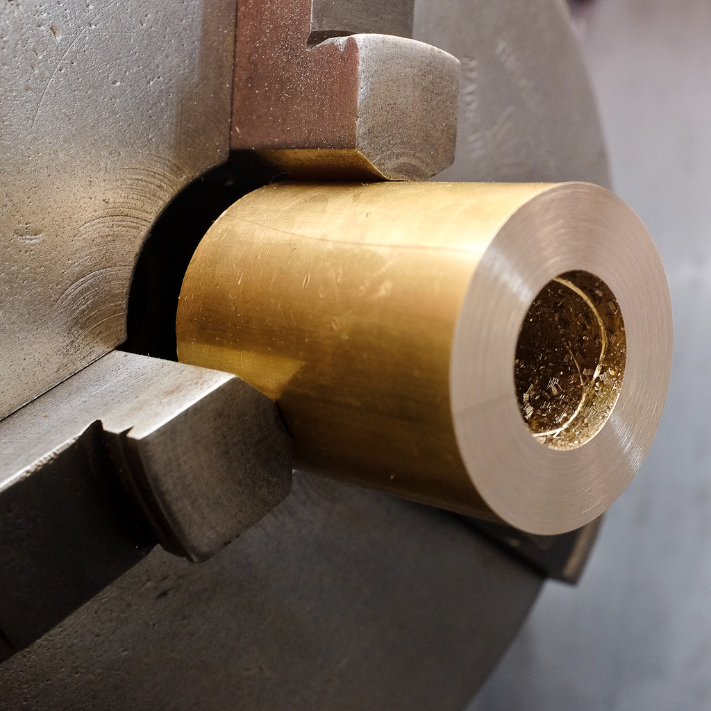
Before parting off the required part, the surface and edges were to be finished for appearance and to remove any sharp edges. There were some areas where the surface looked uneven due to bed wear causing the carriage to not run smoothly . A quick rub with sandpaper while the lathe ran remedied that. Our deburring tool also took off the sharp edge of the ID. Another rub with sandpaper on the edge of the OD created a minuscule chamfer to prevent any cut fingers. Then it was time to make the 8mm spacer. As the insert of the parting tool was 2mm wide, it meant I needed to make the cut at 10mm from the edge of the work piece. Again, the dial indicator was used on the compound rest to measure out the 10mm.
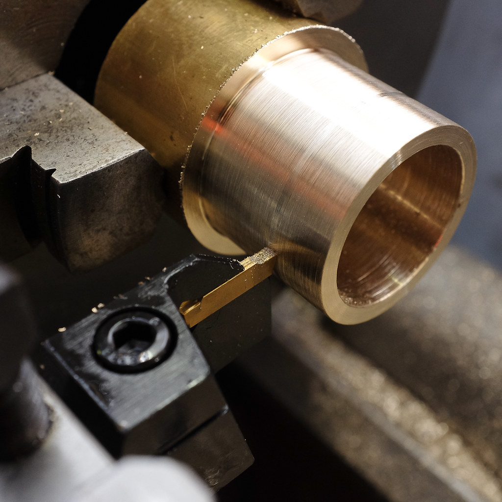
At first, a small groove was cut into the work piece. Sandpaper was used again to create a small chamfer to rid the sharp edge formed. And then power feed to have a smooth cut made. A good hint is to have something held in between the work piece as it’s being parted so it doesn’t fly off and potentially get scratched from landing on swarf.
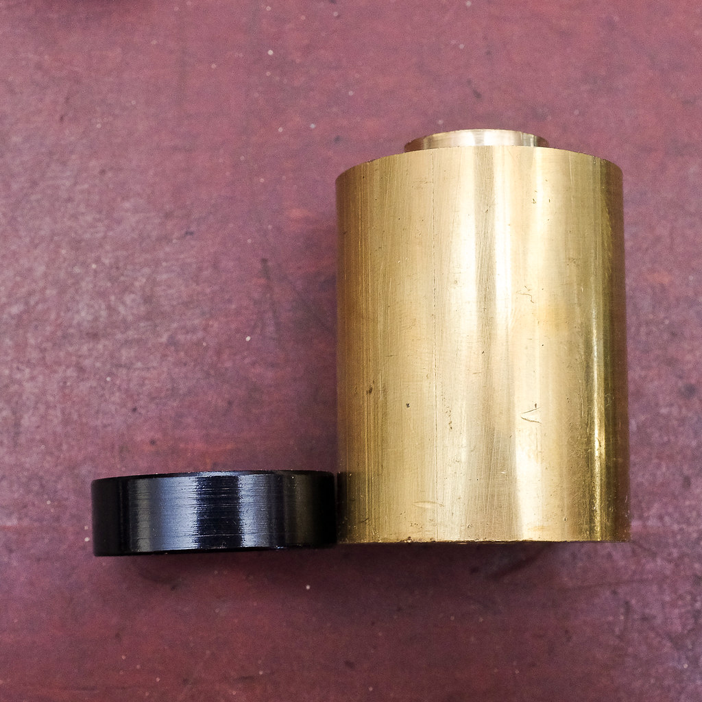
A quick sand on any leftover burrs, and my 8mm spacer was made! And with the remaining material, we made a 5mm and 6.5mm spacer too.
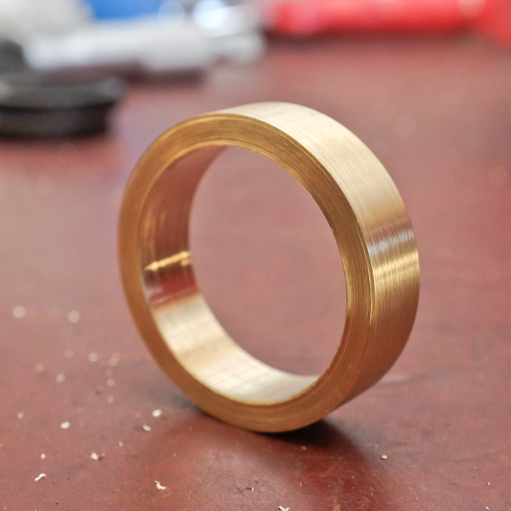
Not bad for my 3rd go on a lathe.

One thought on “Machining headset spacers”